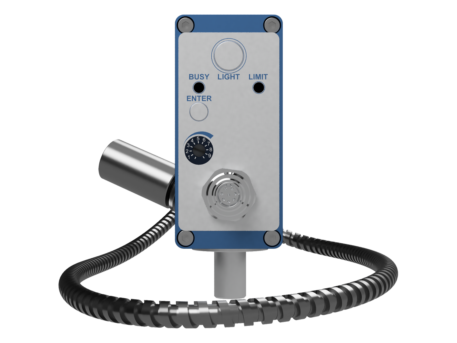
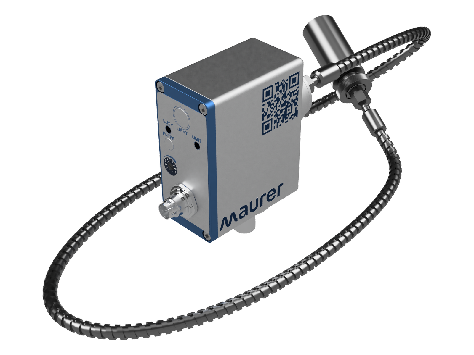
Measuring ranges from 700 °C to 1600°C
1. 700 – 1600 °C
Special measuring ranges upon request
Measuring ranges from 700 °C to 1600°C
1. 700 – 1600 °C
Special measuring ranges upon request
Performance, precision and reliability – you can count on MAURER pyrometers. The compact and easy to use design, as well as a large selection of matching accessories, enables you to quickly integrate the pyrometer into your surroundings.
The most important features and characteristics at a glance:
Scope of Applications
Processing of steel, iron, non-ferrous metal, wires and ceramics; rolling, soldering, welding, transforming, induction heating; vacuum furnace etc.
Fiber optic cables
Configurations
| Spectral range | 0,85 – 1,1 μm | |
| Target marking | Target light | |
| Response time | 100 µsec | |
| Measurement uncertainty | 0,5 % ± 1 °C (ε = 1, Tu = 23°C, T 95 = 1s) | |
| Temperature dependence | 0,01 % / °C | |
| Reproducibility | 0,1 % | |
| Emissivity | 100 – 10 %, adjustable directly at the pyrometer or via interface | |
| Resolution | < 0,1 % at the analogue output < 0,1 °C at the interface | |
| Analogue output | 0 – 20 mA bzw. 4 – 20 mA (Load max. 500 Ω) | |
| Limit output | 1x 24 V 100 mA (open coll.) | |
| Interface | RS 232 ± 50 V isolated or RS 485 ± 70 V isolated | |
| Device connection | 8-pol. plug connector for RS485 7-pol. plug connector for RS232 |
|
| Operating temperature | 0 – 60 °C, Optik 150 °C | |
| Storage temperature | -10 °C – 70 °C | |
| Permissible humidity | 35 – 85 % RF (non condensing) | |
| Supply voltage | 24 V DC ± 10 % | |
| Power consumption | < 100 mA | |
| IP code | IP65 | |
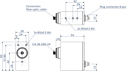
| Dimensions (LxHxW) / Weight | 30 x 65 x 80 mm / 0,19 kg | |
| Other | Maximum memory, peak value memory double, adjustable time and threshold value, erasing after time, external contact, by software, after every measuring object | |
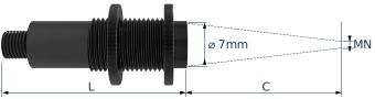 |
Legend</strong | |
| L | Length of opics | |
| C | Distance from optics edge | |
| M | Measurement spot size | |
| Optics | C [mm] | L [mm] | Fiber [µm] | M [mm] |
| VL 50-M12 | 50 | 38 | 200 | 0,7 |
| 400 | 1,4 | |||
| 600 | 2,0 | |||
| VL 100-M12 | 100 | 40 | 200 | 1,0 |
| 400 | 2,0 | |||
| 600 | 3,0 | |||
| VL 150-M12 | 150 | 38 | 200 | 1,4 |
| 400 | 2,7 | |||
| 600 | 4,0 | |||
| VL 200-M12 | 200 | 38 | 200 | 2,0 |
| 400 | 4,0 | |||
| 600 | 6,0 |
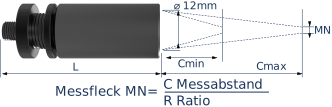 |
Legende</strong | |
| L | Length of optics | |
| C | Distance from optics edge | |
| M | Measurement spot size | |
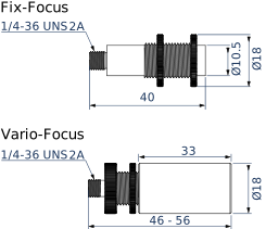
| Optics | Cmin [mm] | Cmax [mm] | L [mm] | Faser [µm] | R Ratio |
| VL-VA N | 65 | 160 | 46 – 56 | 200 | 138 |
| 400 | 69 | ||||
| 600 | 46 | ||||
| VL-VA T | 100 | 5000 | 46 – 56 | 200 | 150 |
| 400 | 75 | ||||
| 600 | 50 |