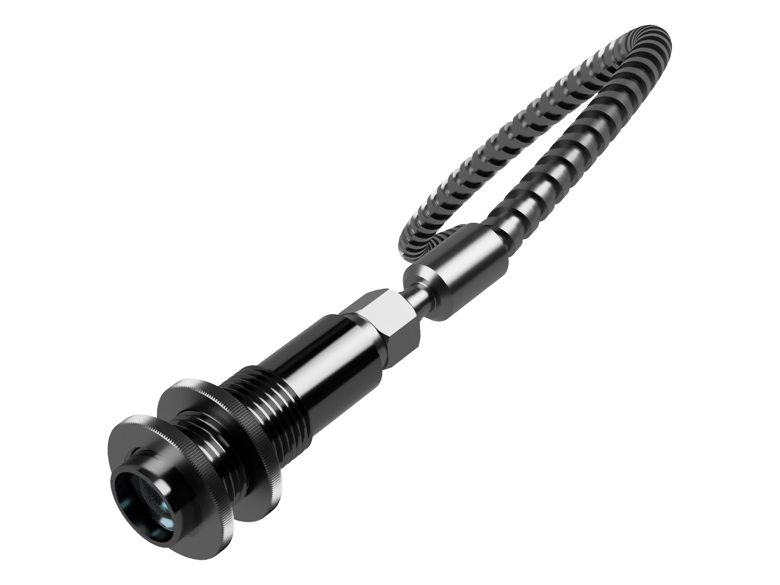
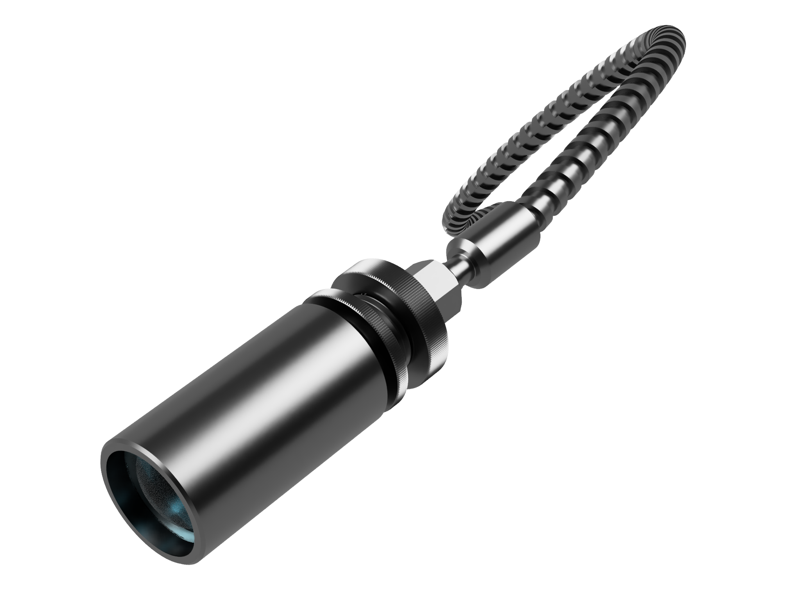
Measuring ranges from 100 °C to 1400°C
1. 100 – 800 °C
2. 150 – 1200 °C
3. 200 – 1400 °C
Special measuring ranges upon request
Performance, precision and reliability – you can count on MAURER pyrometers. Benefit from maximum adaptability by choosing the right optics, accessories and the appropriate interface. Thus our pyrometer fits perfectly into existing systems.
The most important features and characteristics at a glance:
Scope of Applications
Processing of steel, iron, non-ferrous metal, wires and ceramics; rolling, soldering, welding, transforming, induction heating; vacuum furnace etc.
Fiber optic cables
Configurations
| Spectral range | 2,1 μm | |
| Target marking | Target light | |
| Response time | Measuring range 1: 5ms Measuring range 2+3: < 0,5ms | |
| Measurement uncertainty | 0,5 % ± 1 °C (ε = 1, Tu = 23°C, T 95 = 1s) | |
| Temperature dependence | 0,01 % / °C | |
| Reproducibility | 0,1 % | |
| Emissivity | 100 – 10 %, adjustable directly at the pyrometer or via interface | |
| Resolution | < 0,1 % at the analogue output < 0,1 °C at the interface | |
| Analogue output | 0 – 20 mA bzw. 4 – 20 mA (Load max. 500 Ω) | |
| Limit output | 1x 24 V 100 mA (open coll.) | |
| Interface | RS 232 ± 50 V isolated or RS 485 ± 70 V isolated | |
| Device connection | 8-pol. plug connector for RS485 7-pol. plug connector for RS232 |
|
| Operating temperature | 0 – 60 °C, Optik 150 °C | |
| Storage temperature | -10 °C – 70 °C | |
| Permissible humidity | 35 – 85 % RF (non condensing) | |
| Supply voltage | 24 V DC ± 10 % | |
| Power consumption | < 100 mA | |
| IP code | IP65 | |
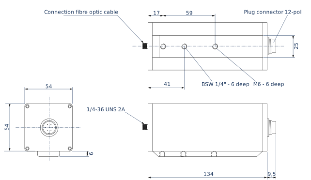
| Dimensions (LxHxW) / Weight | 30 x 65 x 80 mm / 0,19 kg | |
| Other | Maximum memory, peak value memory double, adjustable time and threshold value, erasing after time, external contact, by software, after every measuring object | |
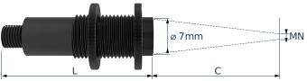 |
Legend</strong | |
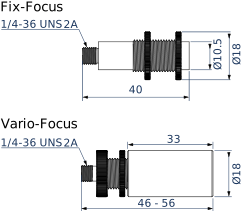
| L | Length of opics | |
| C | Distance from optics edge | |
| M | Measurement spot size | |
| Optics | C [mm] | L [mm] | Fiber [µm] | M [mm] |
| VL 50-M12 | 50 | 38 | 200 | 0,7 |
| 400 | 1,4 | |||
| 600 | 2,0 | |||
| VL 100-M12 | 100 | 40 | 200 | 1,0 |
| 400 | 2,0 | |||
| 600 | 3,0 | |||
| VL 150-M12 | 150 | 38 | 200 | 1,4 |
| 400 | 2,7 | |||
| 600 | 4,0 | |||
| VL 200-M12 | 200 | 38 | 200 | 2,0 |
| 400 | 4,0 | |||
| 600 | 6,0 |
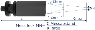 |
Legende</strong | |
| L | Length of optics | |
| C | Distance from optics edge | |
| M | Measurement spot size | |
| Optics | Cmin [mm] | Cmax [mm] | L [mm] | Faser [µm] | R Ratio |
| VL-VA N | 65 | 160 | 46 – 56 | 200 | 138 |
| 400 | 69 | ||||
| 600 | 46 | ||||
| VL-VA T | 100 | 5000 | 46 – 56 | 200 | 150 |
| 400 | 75 | ||||
| 600 | 50 |